Introduction:
The Threat of Transient Overvoltages and the Importance of Standards
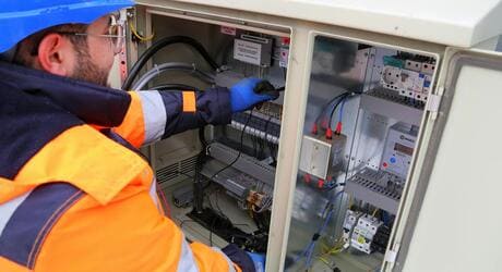
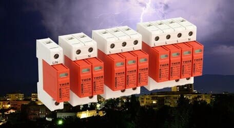
In modern buildings, electrical and electronic equipment is increasingly sensitive to transient overvoltages, commonly known as surges. Whether caused by direct lightning strikes, indirect strikes, or internal system operations (such as switching), surges can lead to irreversible damage to critical equipment, and even cause fires or system downtime. Therefore, establishing a reliable Surge Protective Device (SPD) system that complies with international standards is paramount.
This article will delve into the core principles, standard requirements, and practical strategies for SPD selection and application in building electrical systems, based on the International Electrotechnical Commission (IEC) IEC 60364 series and the German national standard DIN VDE 0100 series.
Core Standards and Principles of Surge Protection
Surge protection is not merely about installing a device; it is a systematic engineering process guided by two major international standards:
1. IEC 60364-4-443: Requirements for Atmospheric Overvoltage Protection
IEC/TC 64 details the methods for building surge protection in Chapter 44 of its publications. IEC 60364-4-443 (corresponding to DIN VDE 0100 Part 443) forms the foundation for atmospheric overvoltage protection.
The core objective of this standard is to limit transient overvoltages to an acceptable level to reduce the risk of failure in the system and connected equipment.
It guides the application of surge arresters by defining Lightning Environmental Conditions (AQ1 to AQ3):
|
Lightning Environmental Condition |
Definition |
Protection Requirement |
|
AQ3 |
Direct effects of lightning (IEC 61024-1) |
Requires the installation of Type I SPD |
|
AQ2 |
Indirect effects of lightning, hazards from power supply systems |
Requires the installation of Type II SPD |
|
AQ1 |
Negligible lightning effect |
SPD installation may be omitted, but internal surges should be considered |
2. IEC 60664-1: Insulation Coordination and Overvoltage Categories (OVC)
IEC 60664-1 (corresponding to DIN VDE 0110-1) is the fundamental standard for ensuring the insulation reliability of equipment in low-voltage systems. It introduces the concept of Insulation Coordination and defines Overvoltage Categories (OVC), which are crucial for guiding SPD selection and installation location 1.
The Overvoltage Category (OVC) is a numerical value that differentiates the equipment's surge withstand capability and its expected installation location:
|
OVC Category |
Typical Installation Location |
Impulse Withstand Voltage (Uimp) |
Protection Requirement |
|
OVC IV |
At the building supply entrance, main distribution board (e.g., electricity meters, main circuit breakers) |
Highest |
Requires Type I SPD protection |
|
OVC III |
Part of the fixed installation (e.g., distribution boards, industrial equipment, permanently connected motors) |
Higher |
Requires Type II SPD protection |
|
OVC II |
Equipment connected to the fixed installation (e.g., household appliances, portable tools) |
General |
Requires Type III SPD protection |
|
OVC I |
Sensitive electronic equipment (e.g., protected electronic circuits) |
Lowest |
Requires Type III SPD protection |
Core Principle: The rated impulse withstand voltage of the equipment must be higher than the transient overvoltage it is likely to be subjected to at its installation point. By installing SPDs, the overvoltage within the system can be limited to a lower level, thereby protecting downstream equipment.
Practical Application: SPD Classification and Cascaded Protection
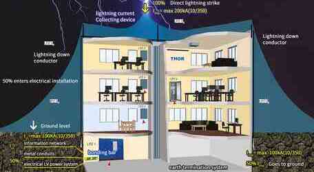
Following the guidance of IEC 60364 and IEC 60664, a surge protection system must adopt the concept of multi-stage protection, also known as Cascaded Protection or Coordinated Protection.
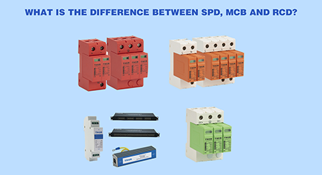
1. SPD Classification (Type I, II, III)
|
SPD Type |
Corresponding Lightning Protection Zone (LPZ) |
Installation Location |
Primary Function |
THOR Electric Recommendation |
|
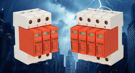
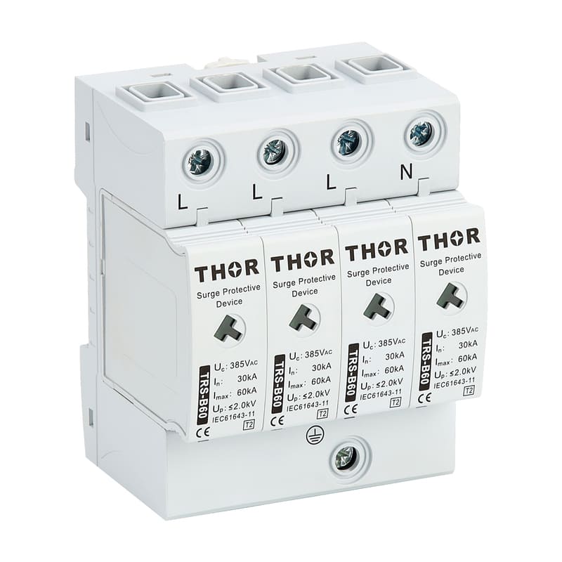
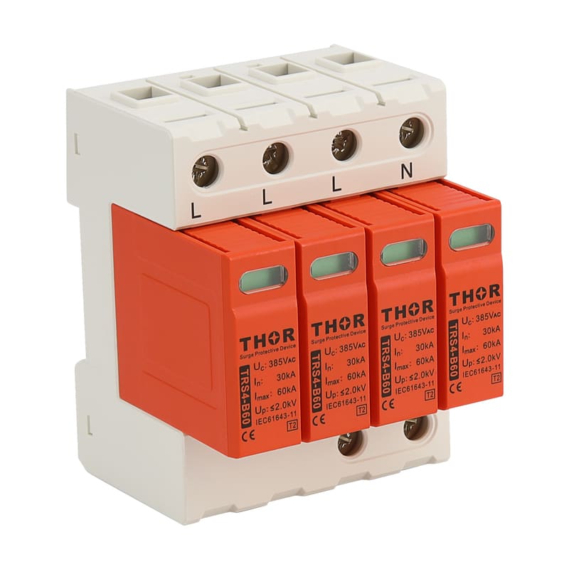
Type I (Class B) |
Boundary of LPZ 0A/0B and LPZ 1 |
Main incoming panel, main distribution board |
Discharges high current from direct lightning strikes (10/350 μs waveform) |
|
|
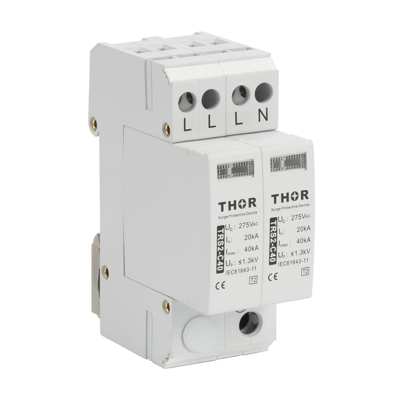
Type II (Class C) |
Boundary of LPZ 1 and LPZ 2 |
Sub-distribution boards, floor distribution boxes |
Absorbs induced lightning and internal surges (8/20 μs waveform) |
|
|
Type III (Class D) |
Boundary of LPZ 2 and LPZ 3 |
Near sensitive loads, at sockets or equipment front-end |
Protects final equipment, limits residual voltage |
TRS-T3 Series |
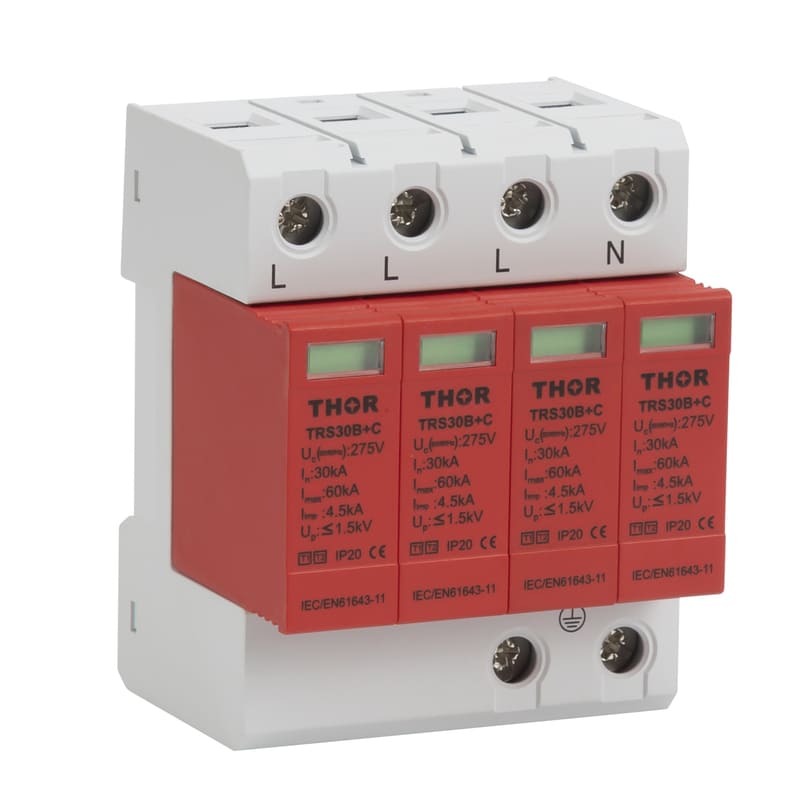
2. The Importance of Cascaded Protection
Cascaded Protection is the key to ensuring the reliability of the entire system. It requires different types of SPDs to coordinate their protection levels to achieve the gradual discharge of energy.
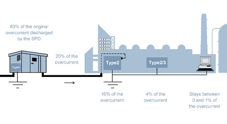
· Energy Distribution: Type I SPDs discharge the majority of the lightning current energy; Type II SPDs absorb residual energy and induced surges; Type III SPDs provide fine protection for sensitive equipment.
· Crucial Point: The length of the conductors (decoupling distance) between the SPDs must be sufficient to ensure that the upstream SPD fully discharges the energy before the downstream SPD operates.
Conclusion: Choose THOR for Reliable Surge Protection
A surge protection system compliant with IEC 60364 and DIN VDE 0100 is the cornerstone for the long-term stable operation of building electrical systems. By understanding the principles of Overvoltage Categories (OVC) and Multi-Stage Protection, you can select the most appropriate SPD products for your project.
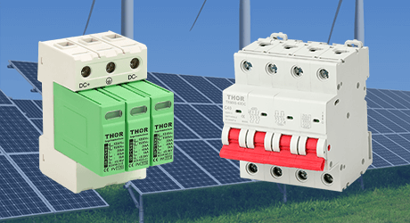
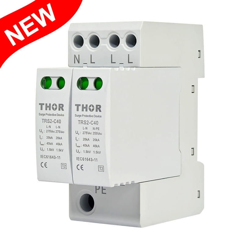
THOR Electric specializes in providing a full range of international standard-compliant surge protection solutions, including Type I, Type II, and Type III SPDs. We offer not only high-quality products but also professional selection consultation and installation guidance to ensure your electrical system is safe from transient overvoltage threats.
Contact us today to receive professional surge protection solution customization services and keep your systems safe from transient overvoltage threats.